ABSTRACT
The objective of this study was to measure liner wall movement and defines the characteristics of pulsation. The cyclic opening and closing of the milking machine liner is called “Pulsation.” The liner opening and closing is a consequence of the differential pressures across the walls of the liner barrel. Liner wall movement was measured in the laboratory and during milking with an analogue laser sensor and a laptop computer equipped with a data acquisition system. Measurements were made in 10-s segments. The first and last cycles of 10 pulsations were dropped from each segment, and the average of eight cycles was used for final analysis.
Opening and closing phases of liner wall movement were characterized at the intersection of 1mmless than fully open and 1 mm greater than fully closed. The ‘D’ phase of the liner was 407 ms, in contrast to the ‘d’ phase of the chamber vacuum of 259 ms with an artificial teat.
Time of liner opening averaged 87 ms with an artificial teat and 98 ms during milking. Liner closure time was 23 ms with an artificial teat and 42 ms during milking.
Liner ratio was 57:43, with a chamber vacuum ratio of 65:35 using an artificial teat. Liner ratio was 58.2:41.8 with a chamber ratio of 64.5:35.5 during milking. This technology can be used to improve liner design and enhance milking performance.
(Key words: data acquisition, liner, vacuum)
Abbreviation key: CCPD = critical collapsing pressure difference, TPPD = touch point pressure difference.
INTRODUCTION
The liner is a critical component of the milking machine. It serves to support the teat from radial expansion and cyclically massages the teat by the application of a compressive force (3). This retards fluid accumulation in the teat tissue, facilitating blood and lymph circulation under conditions of negative pressure. Liner design is also important in udder health, especially as influenced by liner slip (7). Shortened liners increase new infections and result in a form of pulsation failure (6). Pulsation failure consistently results in increased mastitis incidence (12). Pulsation is the cyclic opening and closing of the liner (ISO 3918) (1). Pulsation occurs because of the admission and evacuation of air in the space between the rigid shell and flexible liner known as the teat cup chamber. The liner opening and closing is a consequence of the differential pressures across the walls of the flexible liner barrel (2). The wave form or a graph of pressure changes of the pulsation chamber vacuum is divided into four phases: ‘a’ the increasing vacuum phase, ‘b’ the maximum vacuum phase, ‘c’ the decreasing vacuum phase, and ‘d’ the minimum vacuum phase (1). The pressure changes within the teat cup, including the chamber vacuum and internal liner vacuum cause the liner to open and close below the inserted teat. The vacuum inside the liner is not consistent and varies with the internal volume and relative amounts of air and milk inside the cluster (2). Thus, liner wall movement can be expected to be different during milking, in contrast to a static test. In addition, teat size affects the ‘buckling pressure’ or the point where the liner begins to collapse (3). Buckling pressure is sometimes referred to as the critical collapsing pressure difference (CCPD). A repeatable measure at the point where the liner walls touch is called the touch point pressure difference (TPPD) (10). From the touch point, the liner closes further on the teat, the extent to which depends on the liner material, dimensions, tension, teat size and skin thickness, and vacuum conditions. Due to a continuum of collapse and rapidly changing physical dynamics, measurement is difficult. No standards or methods exist to characterize the forces or extent of liner movement.
Attempts to scientifically characterize liner wall movement have been tried by numerous methods. Thiel and Akam (13) developed an electrical switching device to measure pulsator ratio as defined by liner wallmovement. This report makes clear that pulsation graphs and liner wall position may differ extensively. Caruolo (4) stitched electrodes through the opposing liner walls to determine the closure and separation point of the liner walls. These methods were unable to take measurements during actual milking because of fluid or equipment interference. Reitsma and Breckman (8) fitted a teat cup shell with a linear transducer and measured the liner wall movement in relation to chamber vacuum. They conclude that liner composition and design affect the liner’s response. In addition, the rise and fall times of the liner (opening and closing) are considerably shorter than the rise and fall times of chamber vacuum. They suggest that liner wall movement provides a much better indication of teat cup operation than the pulsation chamber vacuum recordings commonly used in testing milking systems (8). Butler and Adley (2) developed amethod of measuring liner wall movement using video recordings.
Measuring the width of the liner by video camera and the pressure difference across the walls allowed an estimate of the degree and duration of liner collapse. Thiel and Mein (14) used high-speed cine photography in a transparent shell and liner to characterize the milk flow in relation to liner wall movement. They noted that the declining vacuum phase (‘c’ phase), when allowed to decline slowly or rapidly, had little influence (0.01 s) on the rate of liner collapse. Schuiling et al. (11) developed a device using a series of eight light beams that were converted to a light sensitive cell. They contend that measuring liner action gives much more information than measuring pulsation vacuum.
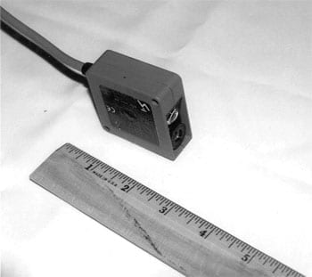
Figure 1. The Wenglor analogue laser sensor YP 06 MGV-P24 (Tettnang, Germany) works with a visible red pulsed laser beam by the triangulation method. The unit measures 50 ◊ 50 ◊ 20 mm. The pictured laser is shown beside a ruler in inches. Supply voltage is 18-30 V DC and analogue output is 0-10.
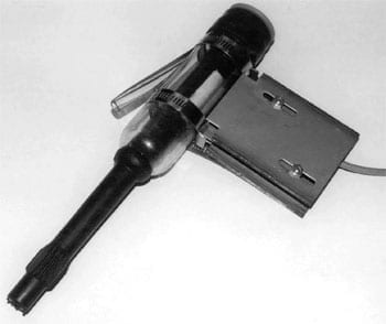
Figure 2. The laser of the Wenglor analogue laser sensor (Tettnang, Germany) is held in place to the transparent teat cup shell by a stainless steel case. The case has adjustable slots to keep the laser within a working range of 40 to 60 mm. Vacuum is measured on the short pulse tube (not shown).
They suggest that too short ‘a’ and ‘c’ phases may cause uncomfortable milking and mastitis. No data are presented in this regard. Schlaiss (10) utilized fiber optics, which gives excellent response characteristics of the liner in relationship to chamber vacuum.
Although teat cup liner performance is critical to machine performance and cow health, data on various liner designs and vacuum conditions in the United States are lacking. The rate of liner collapse is said to influence peak flow (15). Mein (5) and Rosen et al. (9) did not, however, substantiate this observation. The objective of this study was to measure and characterize the rate of liner opening and collapse.
MATERIALS AND METHODS
An IBM compatible laptop computer (Pentium 166 MHz processor) was equipped with a data acquisition system with a 16-channel, 12-bit A/D converter with a capability of up to 1000 Hz per channel (Keithly KPMCI-12 AI, Cleveland, OH). Vacuum sensors with a response time of 1 ms (MICRO SWITCH # 141PC15GL, Freeport, IL) were used to measure the pulsator waveform in the short-pulse tube of the milking machine teat cup. An analogue laser sensor with a response time of 1 ms, a resolution of <20 _m, and a response frequency of 500 Hz (Wenglor # YP 06 MGV-P24, D- 88069 Tettnang, Germany) was clamped to a plastic teat cup to measure liner wall movement (Figures 1 and 2).
Vacuum changes and liner wall movement.
The measuring distance of the laser was 50 mm, with a range of 20 mm. The teat cup liner was marked in the area of the point of laser measurement with a white permanent marking stick (Sanford Corp., Bellwood,IL) to improve reflectance of the liner wall surface to the laser beam. The teat cup liner used for purposes of this report was a DeLaval WC01 in a plastic shell dimensioned to the standard 06 DeLaval shell (Alfa Laval Agri, Kansas City, MO). The teat cup was fitted with a plastic artificial teat dimensioned to ISO Standards (ISO 3918) (1). The point of measurement on the liner wall was as close as possible to the “touch point” of the liner, where the liner walls first touch during the collapse phase. Recordings of liner wall movement and pulse chamber vacuum were taken at 60 pulsations/ min for 10 s duration for analysis. The first and last pulsation cycles were dropped from the analysis and the middle eight pulsation cycles were averaged for final analysis. Pulsation chamber vacuum was also determined with a Surge TRI-SCAN electronic recorder to verify the precision of the Micro Switch transducer and data acquisition system. All comparisons were within ± 2 ms.
RESULTS AND DISCUSSION
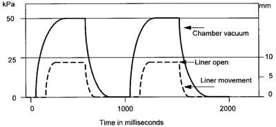
Liner wall movement and vacuum changes in the teat cup chamber are depicted in Figure 3, indicating the four phases of the pulsators’ waveform and method of analysis.
Waveform and description of liner wall movement.
It can be seen that the liner movement follows the vacuum increase in the ‘a’ phase of the vacuum change with a slight delay. Conversely, liner movement precedes the decay in vacuum to atmospheric conditions in the ‘c’ phase of the vacuum waveform.
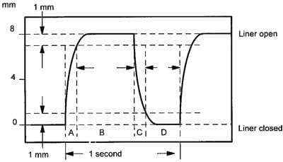
To characterize the waveform of the liner, we used a method similar to describing the waveform of the liner as is used by ISO 3918 for analyzing the pulsator waveform. The two waveforms are differentiated by the use of lowercase letters to characterize the waveform of the vacuum changes and uppercase letters to characterize the waveform of the liner wall position. The suggested intersect is 1 mm from the liner fully open and less than 1 mm to closure at the initial touch point of the liner walls. This contrasts to the characterization of the chamber vacuum utilizing pressure thresholds of __4 kPa. The details of characterizing the waveform of the liner are shown in Figure 4.Table 1 shows the duration of chamber vacuum and liner position in the four phases of pulsation with an artificial teat cup plug. The WC01 liner wall opened in a period of 87 ms, while closure time was 23 ms. In contrast, the chamber vacuum was 146-ms opening (increasing vacuum) and 97-ms closure (decreasing vacuum). Liner ratio was 57:43 with a chamber vacuum ratio of 64.4:35.6.
The ‘b’ phase of the chamber vacuum and the ‘B’ phase of the liner are similar at 498 and 483 ms, respectively. The ‘D’ phase of the liner is considerably longer than the ‘d’ phase in the vacuum chamber (407 vs. 259 ms). The ‘A’ and ‘C’ phases of the liner are shorter than the ‘a’ and ‘c’ chamber vacuum phases. The liner position is related to the vacuum conditions of the pulse chamber; however, the waveform of the pulsator chamber vacuum does not precisely correspond to the liner position.
Table 2 indicates the chamber vacuum at the initiation of each phase of the pulsation cycle. Claw vacuum was 46 kPa. Because the liner wall moves with the differential pressures across the walls of the barrel, each liner has movement characteristics dependent on its physical design. The WC01 liner began to open when chamber vacuum reached 36.7 kPa. The liner was fully open at 45.9 kPa. Thus, the pressure difference across the walls is virtually equal (45.9 vs. 46 kPa). In the ‘c’ phase of the pulsators cycle, the liner begins to close at 34.1 kPa. This point is known as the CCPD. The liner walls touched when chamber vacuum reached 20.5 kPa. This point is known as the TPPD (10).
Table 3 presents the data obtained by milking three cows at different stages of the milking period. Liner wall movement was slightly slower in the opening and closing phases during milking when contrasted to the artificial teat. Opening time increased by 11 ms and closure increased by 19 ms. The ‘B’ phases remained nearly constant, while the ‘C’ phase of liner closure was 19 ms shorter during milking. The ‘D’ phase of the liner was 31 ms shorter during milking compared with the artificial teat.
Chamber ratio was 64.5:35.5 and liner ratio was 58.2:41.8 during milking. Mean claw vacuum was 45 kPa. Thus, there was similarity between the use of a teat cup plug and actual milking conditions.
Some differences between the artificial teat are expected because milk flow changes the interior vacuum of the liner and the artificial teat does not compress under load compared with a normal teat.
Table 4 shows the vacuum at the initiation of each liner phase of the pulsation cycle during milking. The vacuum at the initiation of the ‘B’ and ‘C’ phases of liner position was similar. However, chamber vacuum was lower by 4.8 kPa at the start of opening and 7.8 kPa different when measured at liner closure. These data indicate slightly different liner movement characteristics during milking compared with liner movement with an artificial teat.
CONCLUSIONS
A method of measuring and characterizing liner wall movement is presented. The opening and closing of the liner is much faster than the opening and closing vacuum phases of the teat cup chamber. The opening of the liner was 3.8 times longer than closure time. The ‘D’ phase of the liner was 43% longer than the ‘d’ phase of the chamber vacuum during milking. Thus, the liner is closed for a longer period than may have been previously assumed from interpreting the typical waveform of pulsators. Liner ratio during milking was 58.2:41.8 with a chamber vacuum ratio of 64.5:35.5.The liner position is related to the vacuum conditions of the pulse chamber; however, the waveform of the pulsator does not correspond to the liner position. The use of data acquisition and laser technology more precisely measures liner wall movement and position than do previous methods. This technology can be used to improve liner, shell, and vacuum parameters to enhance machine milking performance. Pulsators might be designed to control the rate of liner wall movement for optimum milking performance. Liner design may also be improved when liner movement characteristics can be quantified. Determination of the TPPD and CCPD of the liner can be measured dynamically. Duration of the compressive load on the teat is a possible parameter needing further research. In addition, liner tension in the shell may be optimized by correlations to milking time. Liner wall movement may be an indicator for the useful life of liners.
REFERENCES
– Anonymous. 1977. International Standard: ISO 3918- 1977-05- 01 Milking Machine Installations, Vocabulary. B-12Q40. Brussels,Belgium.
– Butler, M. C., and A.J.D. Adley. 1993. Measurement of teatcup liner wall movement. J. Dairy Res. 60:1–7.
Journal of Dairy Science Vol. 83, No. 5, 2000
– Butler, M. C., and J. E. Hillerton. 1989. Methods of assess ing teat cup liner performance. J. Agric. Eng. Res. 44:77–86.
– Caruolo, E. V. 1983. Relatively simple method for measuring teatcup liner opening and closing pressures and liner ratio. J.
Dairy Sci. 66:2587–2592.
– Mein, G. A. 1977. Milk flow from the bovine teat in relation to movement of the teatcup liner. Aust. J. Dairy Technol. 32:39–41.
– Mein, G. A., M. R. Brown, and D. M. Williams. 1983. Pulsation failure as a consequence of milking with short teatcup liners. J.
Dairy Res. 50:249–258.
– O’Callaghan, E., J. O’Shea, W. J. Meany, and C. Crowley. 1976. Effect of milking machine vacuum fluctuations and the incidence of mastitis infectivity. Ir. J. Agric. Res. 15:401–417.
– Reitsma, S. Y., and D. K. Breckman. 1985. Measurement and analysis of milking machine teatcup operation. Can. Agric. Eng.
27:91–97.
– Rosen, M. B., E. V. Caruolo, R. D. Mochrie, and D. A. Dickey. 1983. Relationship of pulsation rate, pulsation ratio, and vacuum decrease time tomilking performance. J. Dairy Sci. 66:2580–2586.
10 Schlaiss, G. 1994. Page 98 in Einfluss von modifizierter Zitzengummibewegung auf Milchabgabeparameter und zyklisch Vacuumschwankungen. Dissertation, University of Hohenheim, Germany.
– Schuiling, H. J., F. Neijenhuis, and M. C. Beek-van Maanen. 1994. Pages 148–152 in Liner Monitoring. Proc. Nat. Mastitis Council, Madison, WI.
– Spencer, S. B. 1989. Recent research and developments in machine milkinga review. J. Dairy Sci. 72:1907–1917.
– Thiel, C. C., and D. N. Akam. 1963. A meter for measuring pulsation ratio in milking machines. J. Dairy Res. 31:167–173.
– Thiel, C. C., and G. A. Mein. 1979. Action of the cluster. Page 129 in Machine Milking. Technical Bulletin 1. Natl. Inst. for Res. in Dairying, Reading, UK.
– Whittlestone, W. G., and G. R. Olney. 1962. Machine milking and mastitis. Aust. J. Dairy Technol. 17:205.